this is designed for the about link on the homepage to auto expand
Bernoulli's Principle
Introduction
Bernoulli's Principle is responsible for many things, but the one I think you might have heard of is that it is responsible for keeping airplanes in the air. This is actually true, but it isn't the entire story. Bernoulli's principle is useful for many other things.
Bernoulli's principle is actually a specific case of the general equations that govern fluid flow for the case of laminar flow. This makes it a bit unrealistic since real flow can be chaotic, but dealing with real fluid flow is too complex. Instead, the Bernoulli equations are good enough for our level of analysis, and they simplify things without taking away from the overall picture
The Bernoulli's principle relates pressure in a closed pipe to changes in the height of the pipe and changes in flow velocity. It is derived from the conservation of mechanical energy, as will become obvious when we look at the actual equation behind this principle. There are many effects that come from this principle, but first we should introduce it.
Formula
The principle takes the form of an equation describing the pressure in a pipe at two points, as well as the height difference and the flow velocities at those points.
$$ P_1 + \rho g y_1 + \dfrac12 \rho {v_1}^2 = P_2 + \rho g y_2 + \dfrac12 \rho {v_2}^2 $$ Or, if you prefer:
$$ P_1 + \rho g y_1 + \dfrac12 \rho {v_1}^2 = \textrm{const.} $$ Each of these terms looks very similar to a kind of energy. This is the result of mechanical energy conservation applied to a liquid, and is used very similarly. The first term is pressure, which can be thought of as "pressure energy". The second terms is the potential energy per unit volume of the system, and the third is the kinetic energy per unit volume. Simple!
In assuming that mechanical energy is conserved, we also assume that the liquid has no viscosity, which means this formula is really not too applicable to real liquids. That doesn't stop it from being useful, but is just something to keep in mind.
There are several uses for this formula as well as several specific interesting cases that really demonstrate how the principle works. We'll start by exploring the first and most commonly cited case: the Venturi Effect.
The Venturi Effect
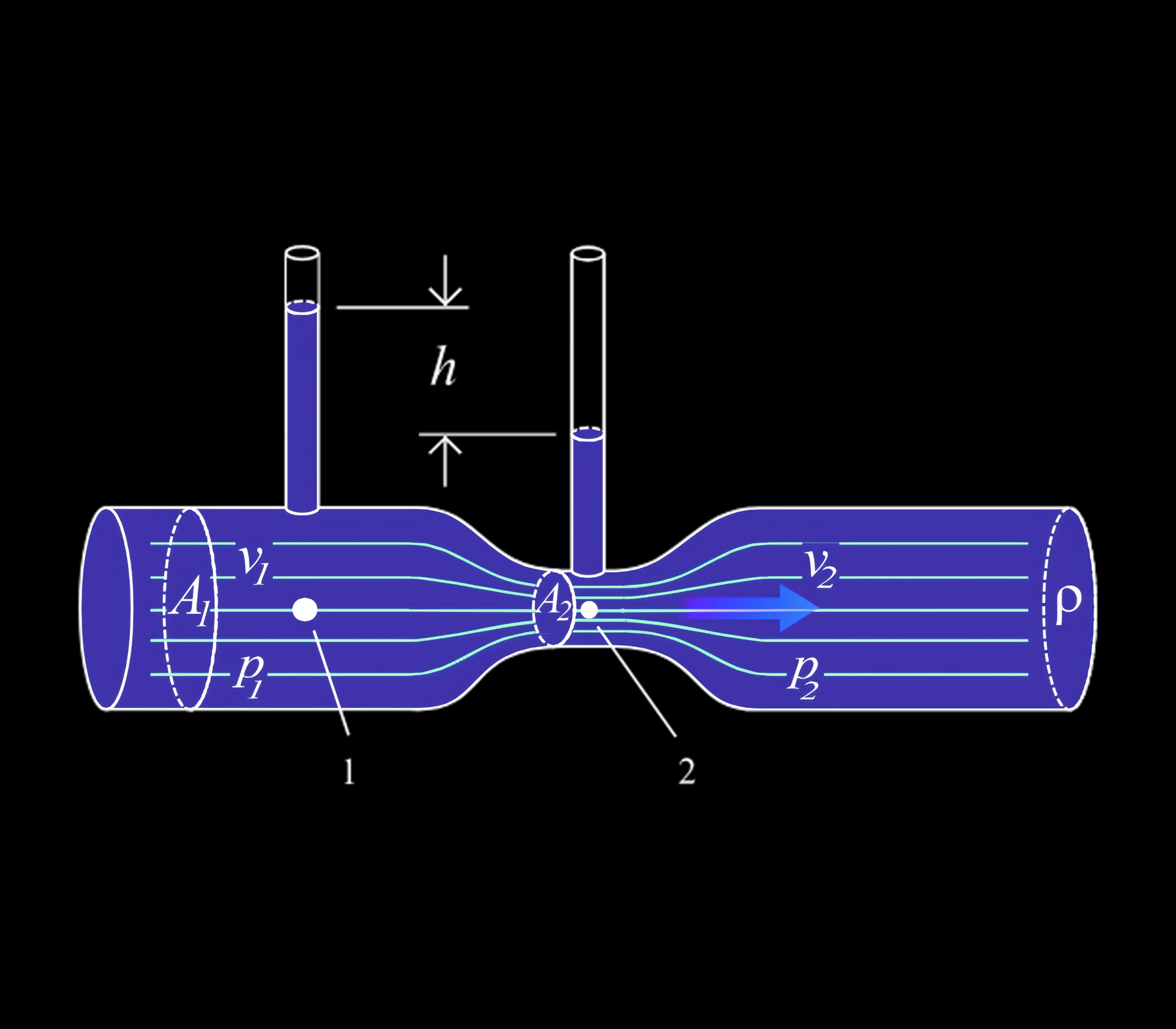
The Venturi Effect involves a pipe of variable width, with small projections upwards the thick and thin sections of the pipe in order to gauge pressure. At the narrow point, the liquid would flow faster than it had at the thick point because the volume flow rate has to remain constant. As a result, the water height in the thin pipe above the narrow section drops lower, indicating lower pressure where the flow velocity is faster.
That might have been confusing, so here's a diagram of the setup I was talking about.
Figure 1: The Venturi Effect. You can evidently see that there is a difference in the heights of the water in the small pipes. The reason for this is that according to the Bernoulli Equation, if the kinetic energy per unit volume portion $\frac12 \rho v^2 $ increases, then the pressure $P$ must decrease accordingly because the sum must remain constant. The potential energy term can be neglected because the pipe doesn't curve up or down. This is evidenced by the water being unable to reach the same height as before in the pipe.
Now, let's put our wits together to actually attempt to solve this problem! This will require everything you've learned so far in fluid dynamics, so it'll definitely be a challenge. However, it will prepare you well for such kinds of problems in the future, so it'll be worth it.
Let's look back at the diagram as labelled. Those are going to be our variables for the problem.
Express the velocity $v_1$ in terms of the areas of the pipes, the height difference $h$ between the water levels, the density of the fluid $\rho$, and any fundamental constants. (This is not easy, so don't beat yourself up if you can't solve it!)
First, I want to define two new variables that we'll use for the sake of calculations. We'll call the absolute heights of the water columns $h_1$ and $h_2$, respectively. This also means that $h = h_1 - h_2 $. Also, since we know atmospheric pressure is present and pushes on both water columns, we will ignore it and instead use gauge pressure for all of our calcuations.
We don't have any potential energy change for the liquid since the center of the tube doesn't go up or down, but we still have pressure. We'll measure pressure to the centers of the tubes, using gauge pressure for simplicity. (We will use the pressure formula for a fluid that we gave in the pressure lesson.)
$$ P_1 = \rho g h_1 $$ $$ P_2 = \rho g h_2 $$ We now want to use Bernoulli's equation, omitting the potential energy terms because they aren't needed.
We can simplify this to make it in terms of $h$ by doing some algebra, subtracting the $\rho g h_2$ term from both sides.
$$ \rho g h + \dfrac12 \rho {v_1}^2 = \dfrac12 \rho {v_2}^2 $$ $$ g h + \dfrac12 {v_1}^2 = \dfrac12 {v_2}^2 $$ Now, we need to relate $v_1$ and $v_2$. This can be done with our flow rate equation. (I told you we'd need it.)
$$A_1 v_1 = A_2 v_2$$ $$v_2 = \dfrac{A_1}{A_2} v_1 $$ $$ g h + \dfrac12 {v_1}^2 = \dfrac12 {v_1}^2 \dfrac{A_1}{A_2}^2 $$ From here, it's just simple algebra to solve for $v_1$.
$$ 2gh = {v_1}^2 \left( \dfrac{A_1}{A_2} ^2 - 1 \right) $$ $$ v_1 = \bbox[3px, border: 0.5px solid white] {\sqrt{ \dfrac{2gh}{\left( \dfrac{A_1}{A_2} ^2 - 1 \right)} } } $$ There we go! You see, we had to use pretty much all the results we learned before as well as Bernoulli's equation to solve this problem.
The math behind the Venturi tube can get very complicated, so we aren't going to talk about it here. The basic principle is very simple, relying on Bernoulli's equation. You would need to invoke formulas that we learned previously, like the gauge pressure formula and the constant flow rate relationship. It's a neat example and shows off exactly what the equation tells us, as well as testing many of the skills we've learned thus far. If you want to see the math, just head over to our algebra-based level and take a gander for yourself.
Application to Aircraft
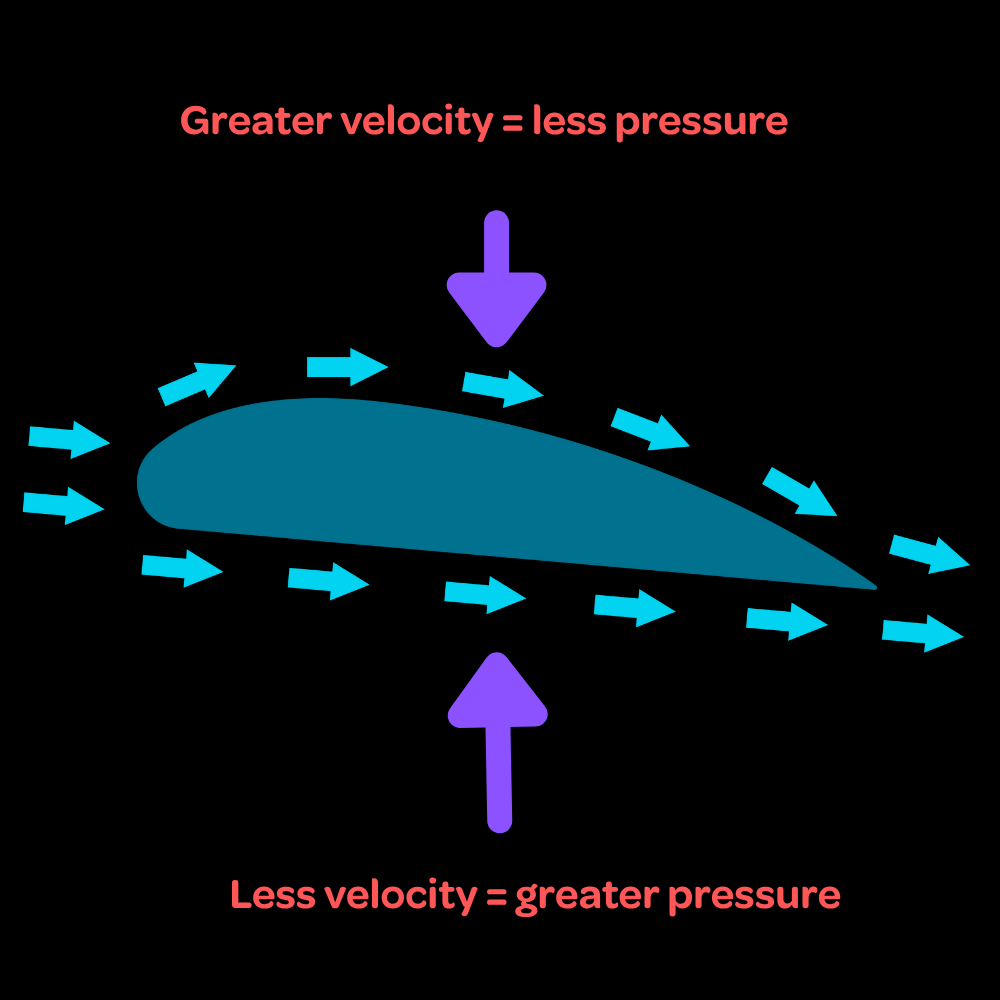
I promised I would talk about how this tied into airplanes, so let's do that now. The Venturi effect is actually the same principle that allows airplanes to fly. The wings of airplanes are what we call airfoils, taking on a specific shape to guide wind flow around them. Specifically, the wing is shaped such that air flows over the top of the wing at a higher speed than it does below the wing.
Figure 2: How the airplane works. (Very oversimplified) According to the Venturi Effect, faster-moving fluid has less pressure, which is exactly what happens. The air pressure on top of the wing is less than below the wing, which means there is a net upwards force on the wing. It is quite literally being pushed up by the air below it. Next time you fly, remember that you are literally being held up by the collisions of air molecules with your plane.
Of course, it's not as simple as that. The engineering behind the airplane is much more complex, but the basic principle is just that the faster-flowing air creates a pressure difference. The exact shape of the wing affects this, but that's more of an engineering thing than a physics one.
It is worth noting, however, that for some aircraft that have wings that are swept very far back or have a delta-wing design, vortices of air can form on the wing surface which can be harnessed to produce what is called vortex lift. This is more of an aviation thing than a physics thing, and it still relies on Bernoulli's principle as the vortices produce a large pressure gradient. So, it still somewhat relies on Bernoulli's principle, but it involves chaotic airflow rather than the laminar airflow of the traditional airfoil.
Let's take a very simplified model of the airplane wing and do one practice problem with it.
Air flows over an airplane wing at $v_1 = 340~\textrm{m/s}$ relative to the plane and under it at $v_2 = 300~\textrm{m/s}$. The plane has a mass of $M = 15000~\textrm{kg}$. What must be the wing area such that the plane can stay in the air? Assume the wing has negligible thickness. (We'll assume the air density where the plane is flying is $\rho = 1.00~\textrm{kg/m}^3$ for simplicity.)
This problem might seem long, but it is actually very straightforward. First off, we can ignore the height difference between the top and bottom of the wing, which makes the problem simpler. Thus, we can write Bernoulli's equation, omitting the potential energy part.
$$ P_1 + \dfrac12 \rho {v_1}^2 = P_2 + \dfrac12 \rho {v_2}^2 $$ We only need the pressure difference $P_2 - P_1 = P$, so we rearrange the equation to match this, subtracting $P_1$ from both sides.
$$ \dfrac12 \rho {v_1}^2 = (P_2 - P_1) + \dfrac12 \rho {v_2}^2 $$ $$ \dfrac12 \rho {v_1}^2 = P + \dfrac12 \rho {v_2}^2 $$ $$ \dfrac12 \rho ({v_1}^2 - {v_2}^2 ) = P$$ Now, we can solve for the pressure numerically.
$$ P = 12800 ~\textrm{Pa} $$ The required force is equal to the weight of the airplane, and the force provided by the pressure is equivalent to the pressure multiplied by the wingspan area (which is what we're trying to find, don't forget!)
$$PA = Mg $$ $$ A = \dfrac{Mg}{P} $$ $$ A = \bbox[3px, border: 0.5px solid white]{11.5 ~\textrm{m}^2 }$$ This is a pretty big area, which shows why larger planes generally will need larger wingspans.
Conclusion
That's the end of the Bernoulli's principle lesson! I obviously didn't cover every single use case of this formula, but I showed what I thought were very good examples showing how the principle applied to the real world. Next, we're going to pivot to something unrelated to what we have been doing before: air resistance and drag. We've been neglecting it and ignoring it, but it's finally time to face it.