Getting Started
- About Us
- Getting Started
- Basic Algebra
- Metric Prefixes
- Trigonometry
- Index/Glossary
Mechanics
Kinematics
- Vectors
- Dimensional Analysis
- Position, Velocity, Acceleration
- One-Dimensional Motion/Free fall
- Two-Dimensional Motion/Projectile Motion
- Relative Velocity
Dynamics
- Newton's Laws
- Forces
- F=ma and Free-body Diagrams
- Inclined Planes and Pulleys
- Spring Forces
Circular Motion and Gravitation
- Centripetal Force/Acceleration
- Fictitious Forces
- Newton's Law of Universal Gravitation
- Kepler's Laws
Energy
- Dot Product
- Definition of "Work"
- Definition of Energy and Energy Conservation
- Types of Equilibrium
- Definition of Power
- Universal Gravitational Potential Energy
Momentum
- Impulse/Momentum Theorem
- Conservation of Linear Momentum
- Center of Mass
- Collisions
- Explosions
Rotation
- Rotational Kinematics
- Torque
- Moment of Inertia
- Rotational Dynamics
- Rolling Without Slipping
- Rotational Kinetic Energy and Angular Momentum
Oscillations
- Simple Harmonic Motion
- Spring-Block Oscillators
- Pendulums
- Other Oscillators
Fluids
- Properties of Fluids
- Pressure
- Fluid Flow
- Bernoulli's Principle
- Air Resistance and Drag
Electricity & Magnetism
Electrostatics
- Electric Charge
- Coulomb's Law
- Electric Fields
- Gauss's Law
Thermodynamics
Inclined Planes and Pulleys
Introduction
It is said that Galileo dropped massive (that is, having mass) balls off of the Leaning Tower of Pisa to prove that the gravitational acceleration was constant for objects of different masses. This is a myth, but what he did do is roll balls down inclined planes of varying steepness. In this section, I hope to teach how to solve these types of problems. We're also going to talk about pulleys, but I don't think there's a good story about that.
The Inclined Plane
First, we consider the quintessential object on an inclined plane with incline angle $\theta$.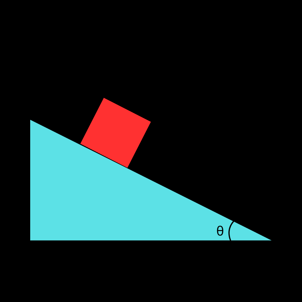
Notice how the normal force $F_n$ is NOT oppositely directed and equal to $mg$ in this case! It will be directed perpendicular to the incline. Now, this diagram is technically accurate, but not very useful.
Determining Axes
Drawing axes will be helpful to tell us how to resolve the forces into components and solve the problem with Newton's second law.
This technically works, but there’s a much better way to solve these kinds of problems. See, in this case you’d have to find the acceleration in both the horizontal and vertical directions, and the trigonometry gets quite messy and unnecessarily repetitive. Instead, think of it this way. The block is constrained to move down the incline. It cannot move perpendicular to the incline (since it can’t move into the incline or rise off of it, at least for this scenario). We can instead define axes perpendicular to and along the incline then:

Now the key is to split the gravitational force into its components along the axes. There are many ways to obtain the angle, but my intuition is that the angle between $mg$ and the axis parallel to the plane is the same as the angle at the top of the plane, so the angle between $mg$ and the vertical axis is simply $\theta$ due to how right triangles Worker. If you need further clarification on why this is, the angle at the top is $\frac{\pi}{2}-\theta$ and the angle of $mg$ with the parallel axis and that with the perpendicular axis are complementary. Again, the exact process by which you get this intuition is not important, but it is very important to know that that angle is $\theta$.
Analysis
Now, the challenge is to find the value of $F_n$ and the acceleration of the block down the incline in terms of $m$, $\theta$, and any constants (hint: the only one we’ll need is $g$).By doing some force analysis, we come to the conclusion that since there is no acceleration perpendicular to the plane, we have the condition:
$F_n = mg\cos(\theta)$.
Down the incline, we have only the component of the gravitational force directed in that direction, so:
$F_{net}=ma=mg\sin\theta$
From this, we easily obtain the result:
$a=g\sin\theta$
That was the most simple inclined plane problem possible, but you can see it still required trigonometry. This fact is common to pretty much all force analysis. If your trigonometry is not great, now would be a good time to brush up on it. We will now add friction into the mix, which will make things a bit more complicated.
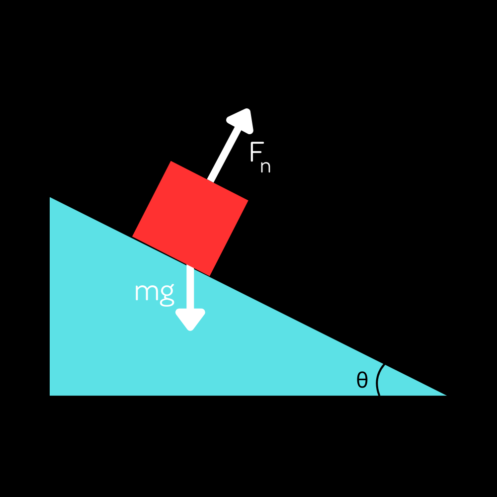
We will consider a quintessential inclined plane, a wedge-shaped object that has an incline angle $\theta$.
While this diagram may look nice and simple, it is unfortunately not very useful for force analysis purposes, even at a conceptual level. Thus, we should make a free-body diagram of the scenario. Technically, I made a force-vector diagram (which places the vectors on an illustration or representation of the scenario) since it would be more visually appealing and connect better to the previous figure.
Now, there is a common misconception that the normal force $F_n$ is directed oppositely to the gravitational force $mg$ and equal to it. This is not true! The normal force is always directed perpendicular to the incline, not vertically. The gravitational force, on the other hand, is always directed vertically downwards. This is very important to keep in mind, as it is a very common error that people make when analyzing inclined planes.
Determining Axes
Now, this diagram is technically accurate, but not very useful. Drawing axes will be helpful to tell us how to look at the forces.While these axes technically are correct and can be used, they aren't very helpful. See, in this case you’d have to find the acceleration in both the horizontal and vertical directions, and the trigonometry gets quite messy and unnecessarily repetitive. To see why another choice of axes would be better, consider the following. The block is forced to move down the incline. It cannot move perpendicular to the incline (since it can’t move into the incline or rise off of it, at least for this scenario). We should then look at the motion of the block along the incline and perpendicular to it, and define our axes that way instead.
Now, we see that the normal force is along one of the axes, so we just need to split the gravitational force along the axes. Qualitatively, we can see that the normal force should equal the component of gravity perpendicular to the incline, and the component of gravity parallel to the incline should be the only force acting down the incline, pulling the block downwards.
To find the exact values of the forces, we need to know the angle $\theta$ of the incline. But since this is conceptual, we won't be doing the problem-solving behind this problem here. Just knowing the results and general idea behind the solution is enough for now.
The normal force is given by the equation:
$F_n = mg\cos(\theta)$.
The acceleration of the block down the incline is given by:
$a=g\sin\theta$.
This was the most simple inclined plane problem possible, but you might notice trigonometric functions in the solutions. This is why at a conceptual level, it is difficult to resolve problems without getting too bogged down in the math. If you believe your trigonometry skills are up to the task, you can see the full solution in our higher difficulties. In any case, we will now consider the same scenario, but with friction.
Inclined Plane (with friction)
Consider the same scenario, but with friction. Now there’s going to be a frictional force directed parallel to the plane. 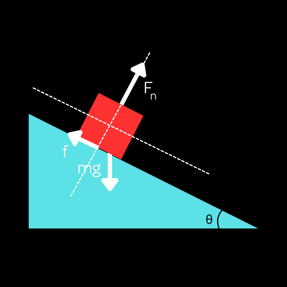
You might think it’s $\mu mg$. After all, that was its value for all previous examples. However, this is an incorrect hasty generalization! Recall the formal definition of the frictional force. It wasn’t $\mu mg$, but rather $\mu F_n$! It was merely that $mg=F_n$ held for all of our previous problems. Now that we have that common misconception cleared up, we can now write the value of the frictional force:
$f=\mu F_n=\mu mg\cos\theta$
where we established that $F_n=mg\cos\theta$ for an inclined plane.
For the block to remain at rest, there must be zero net force parallel to the plane. We can ignore the perpendicular direction since we know the forces along that axis must be in equilibrium (we don’t see the block levitate or sink into the plane). From this, we write:
$mg\sin\theta=F_s$ where
$F_s=\mu mg\cos\theta$
This simplifies to:
$\sin\theta=\mu \cos\theta$
Dividing both sides by $\cos\theta$ gives us (remember your trig identities!):
$\mu=\tan\theta$
This is the minimum coefficient of static friction required to keep the block at rest on the incline. This is a neat result, and it’s quite useful at times as well. To top it off, the derivation isn’t too complex either (you’ll see some very messy derivations later on). T hat’s about it for inclined planes right now. It’s really just force analysis transposed onto a sloped surface. 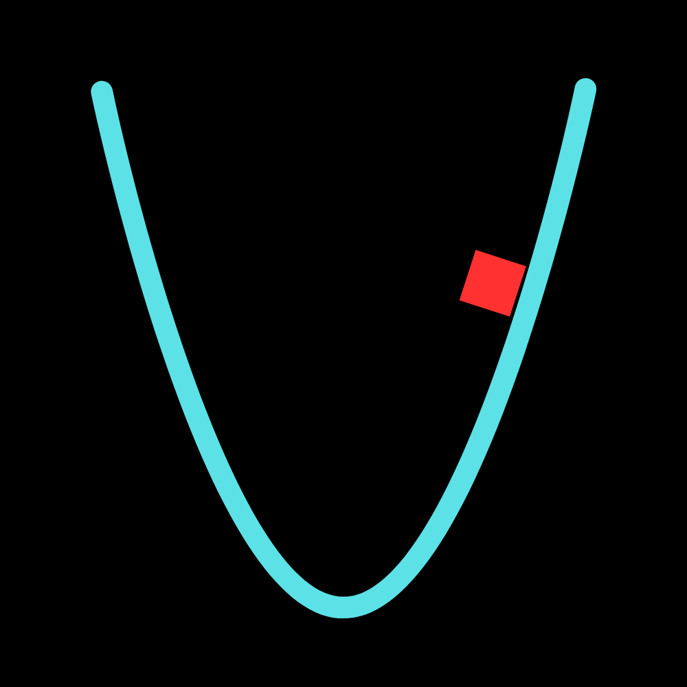
The incline angle at each point is related to the slope of the curve at each point. You calculus students should be jumping to realize that this is the derivative of the function at each point. (If you're not, you should be! This is one of the very first things you learn in calculus.) The slope of the curve at each point is given by the derivative of the function, which is:
$\dfrac{dy}{dx}=2Cx$
Now, what does the slope exactly have to do with the incline angle? Well, the slope is (instantaneous) rise over run, which astute observers will realize is the exact definition of the tangent of the angle of the incline. Thus, we can write:
$\tan\theta=2Cx$
This means that the incline angle at each point is given by:
$\theta=\arctan(2Cx)$
Now, we can find the acceleration of the block at each point. The acceleration is given by the component of gravity down the incline, which we have derived before. If you don't remember this, review the earlier parts of the lesson.
$a=g\sin\theta$
Now, here comes the trigonometry. Since we know the tangent, we can find the sine by drawing an arbitrary triangle where the tangent is equal to $2Cx$. This is a common trigonometric technique and I assume you know it if you know calculus. 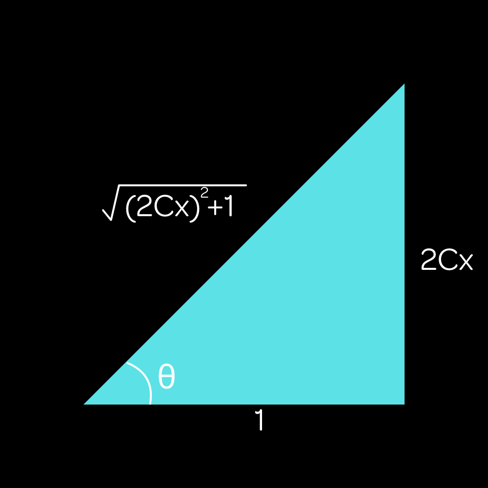
$\sin\theta=\dfrac{2Cx}{\sqrt{(2Cx)^2+1}}$
Now, we can plug this into the equation for acceleration to get:
$a=g\sin\theta=g\dfrac{2Cx}{\sqrt{(2Cx)^2+1}}$
This looks like a final answer, but the last step is to add a negative sign. The acceleration is negative (toward the origin) when displacement is positive and positive when displacement is negative. So this result actually works on both halves of the parabola!
$a=-g\dfrac{2Cx}{\sqrt{(2Cx)^2+1}}$
Couldn't be simpler. (That was sarcasm.) This is certainly a result, but it is not very useful in practice. It is very difficult to solve problems with this, and it is generally not worth the effort. You might think that you can integrate this to find the velocity and position of the block, but that is actually not entirely true. Since the incline is curved, the direction of the acceleration will always be changing, so if you want to integrate this you need to take into account the changing direction of the acceleration. This is far beyond the scope of this lesson, and it is not worth the effort because we will show that there is a much easier way to solve for velocity at any point with energy conservation. But that's later on. Inclined Planes (with friction)
Consider the exact same scenario, but now with friction thrown in. The force-vector diagram now looks like this:
You want to first notice that friction is parallel to the incline and not just horizontal. Most people have an easier time understanding this than the previous note about the normal force, but it is still important to keep in mind.
If you've ever placed something on an incline, you know that normally it'll just slide down the incline. However, if the friction is enough and the incline is not too steep, the object will remain at rest on the incline. You can try this yourself with a book on a tilted surface like a plank of wood.
There is a mathematical derivation of the minimum coefficient of static friction required to keep the block at rest on the incline, but I will not be going over it here. It is not too complex, but it is a bit messy and requires some trig identities. If you want to see it, you can check out the higher difficulties. The general idea is that the frictional force must equal the component of gravity parallel to the incline, and the normal force is still $F_n=mg\cos\theta$.
The result is that the minimum static friction is dependent on nothing but the angle of the incline, which may be a shockingly simple result. However, if you think about it, it makes sense. The steeper the incline is, the rougher it needs to be to keep an object at rest on it. A rough plank of cut wood will easily keep a book at rest on it, but a smoother marble or tile slab will not, even at the same angle. The exact mathematical minimum condition is:
$\mu=\tan\theta$.
In any case, this is all there really is to inclined planes. It’s just force analysis on a sloped surface, and it’s not too complex once you get the hang of it. Now, we'll move on to pulleys, which are a bit more complex but still not horrible. But first, something interactive.
We've already talked about the inclined plane with and without friction, which covers most of the cases that we need to know. Therefore, now would be a good time to get some "hands-on" experience with how inclined planes work, in order to build intuition and confidence in our results. Here's an inclined plane demo you can play around with. See if you can reproduce all the results and behaviors we've talked about previously!Inclined Plane Demo
The pulley is a simple device often used to lift heavy objects. It dates back from ancient times, being one of the early simple machines. But since this is a physics lesson and not a history or engineering lesson, we don't care about that. I'm here to show you how to analyze the forces behind pulleys and how to solve problems involving them.
The Pulley
For now, we only consider massless, frictionless pulleys and massless strings. Let’s use a simple one-pulley system to demonstrate the mechanics behind the pulley.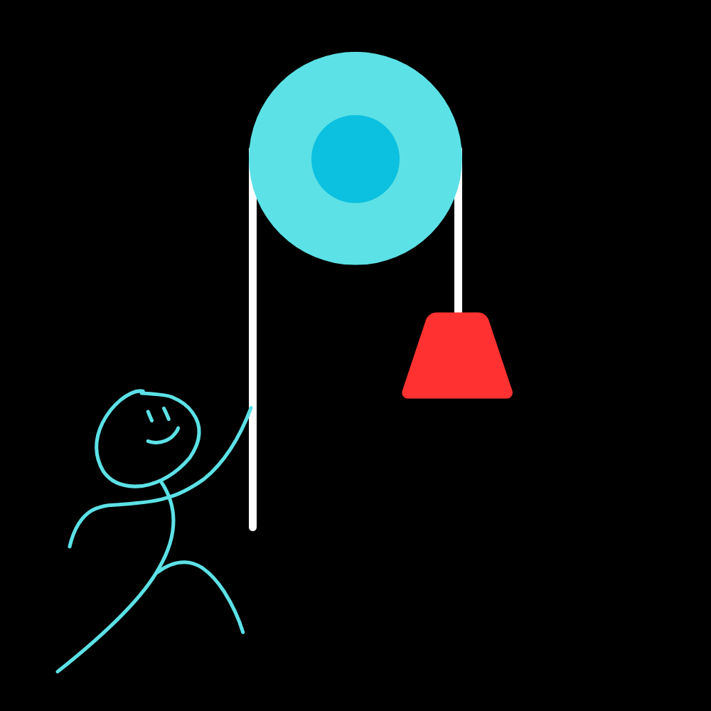
Suppose the stick figure pulls down with force F. Then we draw some forces directly onto the diagram:
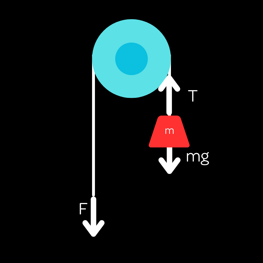
Now to find the tension force $T$, all we have to do is to realize that the tension in a string is constant throughout its length. Note that this isn’t necessarily true for a massive (having mass) rope. Then, seeing as the force applied to the string is $F$, we conclude that $F=T$ for the scenario. Intuitively, if you pull down with a force equal in magnitude to the block’s weight, it will remain at rest in the air. You can then do all sorts of force analysis.
Atwood Machines
Now I’d like to consider the Atwood machine where two differently-massed objects hang from either side of a pulley.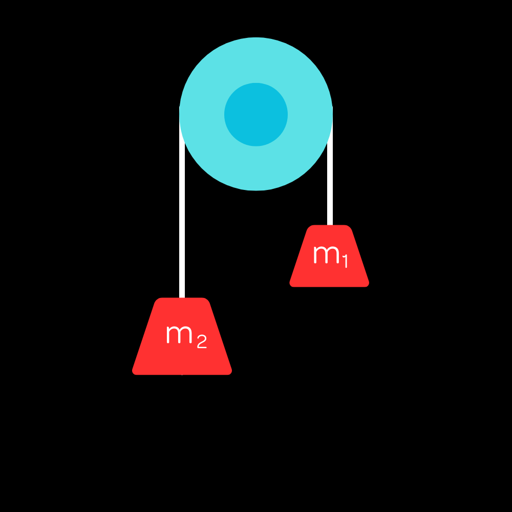
From experience, you should know that the more massive block will move downward and the less massive one will rise. This is useful to keep in mind. Even if you assume the directions of acceleration incorrectly, the answer will be correct except for a sign error (which is often not important in physics) provided you keep the same assumptions throughout your calculations.
We will do quantitative force analysis on this scenario now.
To do this problem, we set the tension at an arbitrary value $T$ since we cannot gauge it directly from the diagram. For the first block, we know that $T>m_1g$ since the block accelerates upward. Therefore, we write:
$T-m_1g=m_1a_1$
Following by similar logic, $m_2g-T=m_2a_2$
Now, we need to relate the accelerations of the two blocks. The key is to recongize that they are connected by a string, so they must have the same magnitude of acceleration. We can then write $a_1=a_2=a$.
Now, we can add the two equations together to eliminate $T$:
$m_2g-m_1g=(m_1+m_2)a$
This gives us the acceleration of the blocks:
$a=\dfrac{(m_2-m_1)g}{(m_1+m_2)}$
We can also then find the tension force by plugging this value for $a$ into one of our two previously derived equations:
$T=m_1a+m_1g$
$T=m_1g(\frac{m_2-m_1}{m_1+m_2}+1)$
$T=\frac{2m_1m_2g}{m_1+m_2}$
You can verify this result by plugging into the other equation and seeing that it comes up with an equivalent result, or by eliminating $a$ in the initial system of equations to solve for $T$.
Now you may wonder what the force on the pulley is. Well, if we look at the pulley, there is a force $T$ pulling downward on each side, so it is simply $2T$. We didn’t consider this in the above scenario since the pulley was fixed, but this has some very useful implications later on.
Next, we will consider a system of many pulleys, often used to lift heavy objects. Since we are dealing with things conceptually here, we will not do a full mathematical force analysis of the scenario. Instead, we will try to develop our intuition for these kinds of problems. From our everyday experience, we know that the system will tend to accelerate in the direction of the heavier object. That is, the heavier block will move down while the lighter one moves up.
In this scenario, we will assume that $m_2 > m_1$ for simplicity. Since we are not concerned with the mathematics of the problem, we can analyze the scenario qualitatively. First, we should note that the two masses must move together since they are connected by a string. This means the acceleration of both blocks is the same!
There's not much more to qualitatively analyze about the scenario, so if you want the actual results you can check out our higher difficulties.
Now, we will move on to talk about a more complex system of pulleys, often used to lift heavy objects.
More Complex Pulley Systems
Something more interesting happens when there is more than one pulley involved, specifically when that second pulley is allowed to move. For instance, take this scenario: 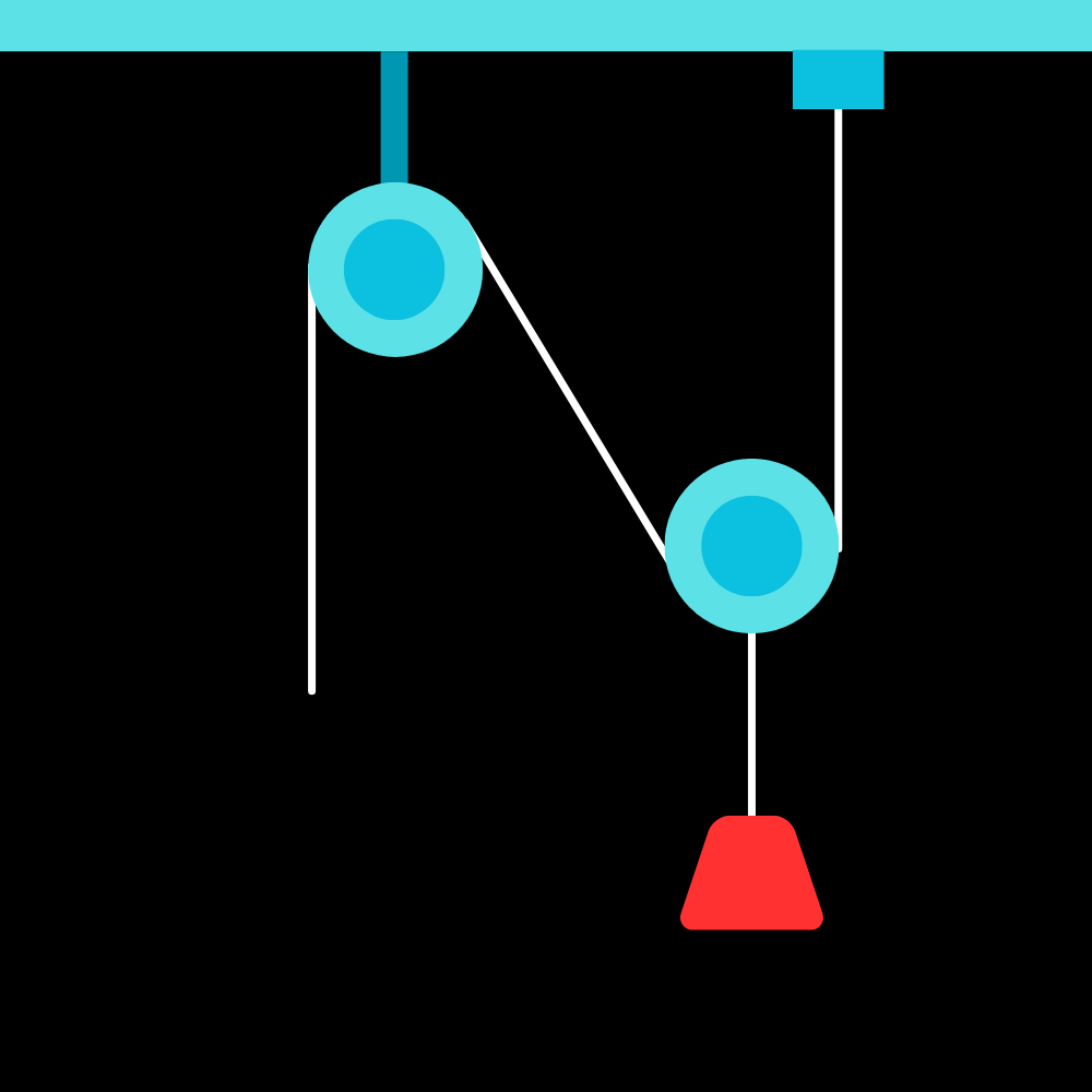
This kind of device is called a block and tackle, and it is often used to lift heavy objects. Take a good look at the diagram and see if you can figure out why it is so useful.
The top left pulley is not allowed to move, but the bottom right one is allowed to move vertically. What is the force needed to lift the block of mass $m$?
This problem introduces the concept of conservation of string. If one pulls the string down a small length $l$, how far does the pulley rise? Well, the pulley is not directly attached to a string, but rather has two segments of string around it. So, if a length $l$ is pulled downwards, the pulley only rises by $l/2$. This, in turn, means that the acceleration of the pulley upward is half of the “acceleration” of the string. If you look closely, the pulley is actually acted upon by two tension forces, one from each side of the string. Thus an applied force of only $mg/2$ is needed.
Mass $m$ is connected to the pulley, so we can essentially treat them as one object and write:
$2T-mg=ma_1$ (Remember that the $2T$ term arises because both segments of string on the pulley apply a force of $T$ upward.)
As for mass $M$, we can simply write:
$Mg-T=Ma_2$
Now we need to use the result from conservation of string to reason that $a_1=a_2/2$, relating the two accelerations. I’ll set $a_1=a$ for convenience.
$2T-mg=ma$
$Mg-T=2Ma$
Now we need to eliminate $T$, so we’ll do a little algebraic manipulation to derive the result:
$(2M-m)g=(4M+m)a$
This gives us the acceleration of the first block:
$a=a_1=\frac{2M-m}{4M+m}g$
And the acceleration of the second block is simply half of this:
$a_2=\frac {2M-m}{2M+m/2}g$
Solving for $a_2$ first is also a completely valid way to solve this problem, and you should arrive at the same answer. Conclusion
This is one of the more difficult scenarios involving pulleys and is not entirely too common, but it is the entire reason why pulleys are so useful in the real world. Additionally (Eric speaking), you should be prepared to do difficult problems if you are interested in physics. This subject is very demanding, and I expect nothing less than the best from you. It doesn't matter if you get the answer wrong, as long as you try your best and learn from your mistakes. Effort is practically required for this course.
With that little rant out of the way, we will now move onto adding more complexity to this scenario with the introduction of a new force that can change, the spring force! This is our first variable force and will expand our horizons for force analysis significantly. The astute observer will notice that the pulley on the right is not fixed, but rather is allowed to move vertically. This is a very important distinction, as it allows us to lift heavy objects with a much smaller force than the weight of the object. Take a close look at the exact setup of the pulley. It has two segments of string on either side of it, meaning experiences double the force that is exerted on the free end of the string. This lets us lift heavier objects with smaller forces.
Now is also a good time to introduce the concept of conservation of string. If one pulls the string down a small length $l$, how far does the pulley rise? Well, the pulley is not directly attached to a string, but rather has two segments of string around it. So, if a length $l$ is pulled downwards, the pulley only rises by $l/2$. This may be difficult to visualize, but if you keep thinking about the physical setup of the pulley, it should make sense. This, in turn, means that the acceleration of the pulley upward is half of the “acceleration” of the string. Conclusion
That's pretty much all there is to say about this scenario without getting into the mathematics of it. There are many similar machines that involve pulleys that are allowed to move, but they all follow the same principles. At a conceptual level, it is sufficient to know where the forces are acting and qualitatively how the objects move.
Now that we have discussed the two most common types of setups in physics, we can add another kind of force to it: that from a spring, which is a coil of metal that is bouncy. (But you already knew that.) You're almost at the end of this unit, so let's keep going!